
The transition toward higher motor efficiency standards continues to reshape the global electric motor industry. As regions adopt increasingly strict energy regulations—such as IEC efficiency classes and MEPS requirements—motor manufacturers must redesign core assemblies to reduce losses and enhance magnetic performance. The YE2 motor series, widely used in industrial machinery and general-purpose drive systems, demands stable efficiency, low noise, and reliable long-term operation.
At the center of this efficiency improvement is the optimization of silicon steel sheet motor laminations. YE2 silicon steel sheet motor laminations play a decisive role in determining magnetic flux behavior, thermal response, and energy consumption. As industrial users seek better productivity with reduced electricity cost, demand for laminations with lower core loss, improved permeability, and tighter dimensional tolerances continues to rise.
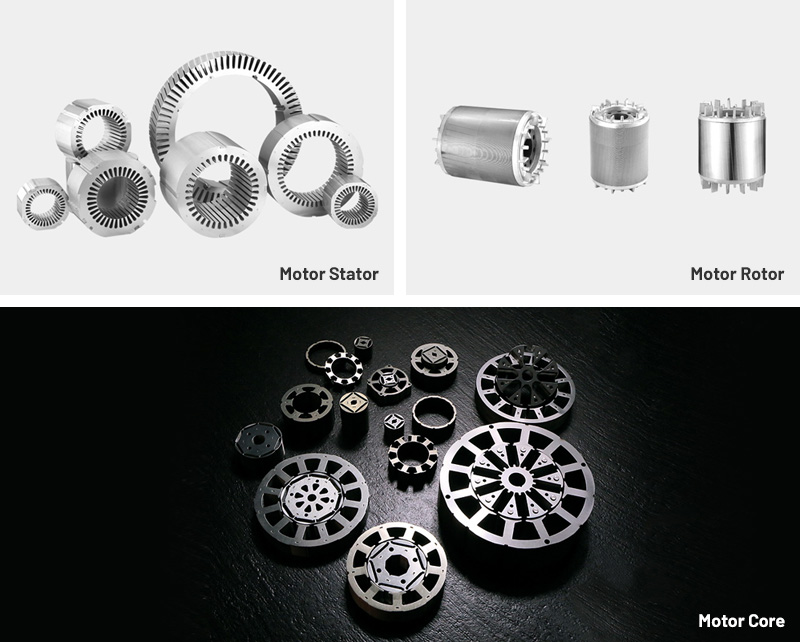
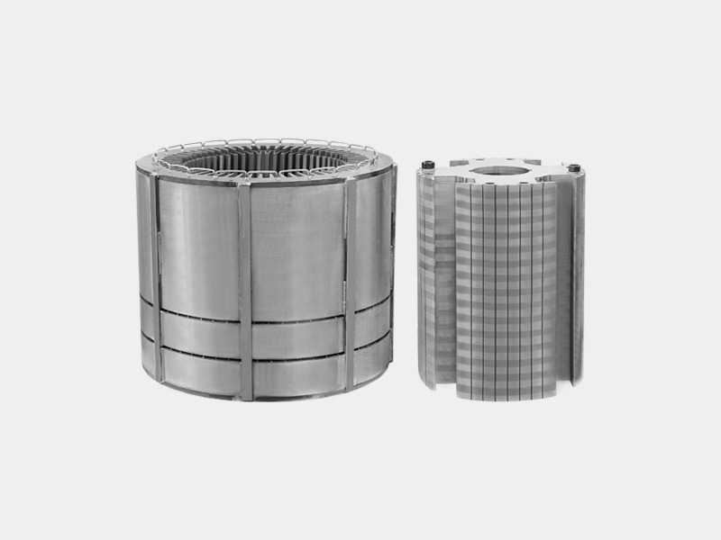
Motor laminations create the magnetic path inside the stator and rotor. By stacking thin silicon steel sheets coated with insulation, engineers minimize eddy-current formation and maintain stable flux distribution under continuous operation.
Electrical steel is selected for its balance of magnetic permeability, resistivity, and mechanical stability. In YE2 laminations, it must support:
Reduced hysteresis loss
Low eddy-current generation
Consistent magnetic saturation levels
High stability over wide temperature ranges
A key technical feature is the insulation coating applied on each steel sheet. It prevents inter-layer conduction, ensures proper heat dissipation, and improves stacking factor, which directly affects motor output and efficiency.
YE2 laminations primarily use non-oriented silicon steel with uniform magnetic properties across all rolling directions. The material typically includes 2–3% silicon to improve resistivity and reduce losses. Performance indicators include:
Core loss at specific frequencies
Magnetic permeability
Thickness tolerance
Coating insulation class
Punching die compatibility
The design of YE2 motor laminations depends on motor size, slot shape, and electromagnetic design requirements. Key structural considerations include:
Slot geometry to ensure optimal copper fill and stable winding distribution
Stack thickness based on motor output torque and thermal capacity
Rotor bar cavity for cast-aluminum rotor systems used in YE2 motors
Ventilation structures, when included, to enhance cooling
High-accuracy progressive dies are used to punch each silicon steel sheet with consistent geometry. Critical requirements include:
Low burr height
Minimal material distortion
Uniform slot width
Accurate inner and outer diameter tolerances
Stacks may be assembled through:
TIG welding
Laser welding
Core bonding
Mechanical riveting
Each method influences rotor balance, magnetic uniformity, and noise performance.
The insulation layer requires controlled curing to maintain breakdown voltage and prevent degradation during thermal cycling.
YE2 laminations are designed to deliver:
Lower core losses at 50/60 Hz
Higher efficiency under IEC IE2/IE3 requirements
Improved magnetic permeability
Reduced noise and vibration
Stable heat dissipation during continuous duty
Extended lifespan for bearings and winding insulation
Because motors operate across variable load conditions, core materials with stable loss characteristics are essential for predictable performance.
Changes in alloy composition, coating type, or grade consistency significantly affect loss performance. High-purity steel improves permeability and reduces hysteresis loss.
Die wear, press tonnage, and feeding systems affect dimensional repeatability. Micro-burrs can increase eddy-current paths and introduce additional heat.
Breakdown voltage, adhesion, humidity resistance, and thermal stability determine long-term reliability. Inadequate coatings accelerate lamination shorting and increased loss.
Higher stack factor increases usable magnetic cross-section, improving torque density and reducing motor size for a given output.
For die-cast rotors, aluminum flow characteristics must be uniform to avoid imbalance and inconsistent magnetic fields.
Some manufacturers apply stress-relief annealing to restore magnetic properties after punching, which significantly influences permeability and loss.
Selecting the right supplier for YE2 silicon steel sheet motor laminations impacts motor reliability, compliance, and production efficiency. Important criteria include:
Suppliers should provide steel certificates, coating specifications, and batch traceability records.
Advanced progressive die technology ensures:
High punching lifespan
Improved tolerances
Reduced scrap rate
Better consistency between batches
Suppliers should implement dimensional inspection, burr measurement, coating integrity testing, and stack factor evaluation.
Large-volume motor manufacturers require a predictable supply of laminations with low lead times and minimized handling damage.
Laminations should support motor designs that meet:
IEC 60034
GB 18613
MEPS Standards
Despite advances in materials and manufacturing, several challenges affect the production and application of YE2 silicon steel sheet motor laminations:
Punching dies degrade over time, causing slot width deviation and burr increase, which negatively impacts magnetic performance.
Mechanical stress can crack the insulation coating, reducing resistance between layers.
Poor stacking or welding methods may introduce imbalance, causing vibration and noise during operation.
Fluctuations in steel supplier quality lead to variable magnetic characteristics across production runs.
Continuous high-load operation accelerates coating degradation and increases core loss.
YE2 silicon steel sheet motor laminations are widely used across industrial sectors, including:
Reliable torque delivery and low thermal rise are essential for heavy-duty pumping applications.
Low-noise performance and stable efficiency support long-term operation in commercial and industrial ventilation.
Precise magnetic performance ensures smoother operation of conveyors, robotics, and variable-speed systems.
Stable magnetic fields minimize vibration and help improve machining accuracy.
YE2 motors are common in factories, workshops, and agricultural machinery requiring high efficiency and dependable durability.
The industry is moving toward new grades of electrical steel with improved permeability and reduced hysteresis loss.
Laser cutting enhances precision for prototypes and high-efficiency motors, reducing mechanical stress and burr formation.
As high-speed compressors and turbo blowers become more common, laminations must support higher frequencies and lower eddy-current losses.
Automated inspection systems are increasingly used to measure burr height, coating defects, and dimensional accuracy.
Manufacturers are adopting more efficient recycling methods for scrap silicon steel to reduce environmental impact.
FAQ: YE2 Silicon Steel Sheet Motor Laminations
Core loss, permeability, coating quality, and punching accuracy are the primary performance factors.
It prevents inter-layer conduction, reduces eddy-current losses, and ensures long-term thermal stability.
Tooling must be monitored continuously; service intervals depend on production volume and burr inspection results.
Yes. High-quality laminations directly reduce core losses and improve overall efficiency in YE2 motors.
Product Category
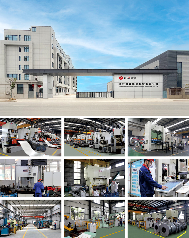
Comprehensive Strength
Customization Process
1. Customer Communication: To communicate, And record customer requirements in detail.
2. Design Of Scheme: Design according to the requirements put forward by customers, and maintain communication with customers.
3. Confirm The Design: Submit design proposal, and based on customer feedback, Further revision until the final version.
4. Production: Select the right model, And according to the design of production.
5. Testing & Quality Inspection: Strictly test whether the products meet the standards, Eliminate all quality problems.
6. Shipment: Package the products that pass the inspection, And deliver the goods to the customer's address.
7. Customer Return Visit: Regular return visits to customers, Listen to customer feedback.

 Mobile: +86 13738592999
 Telephone: +86(576) 89307999
 E-mail: sales@zjxinzheng.com
 Address: Coastal Industrial City, Sanmen
County, Taizhou City, Zhejiang Province, China
Copyright © Zhejiang Xinzheng Electromechanical Technology Co., Ltd. All Rights Reserved.
This website uses cookies to ensure you get the best experience on our website.


 WhatsApp
 Phone
Phone