
The transition toward quieter and more energy-efficient electric motors has accelerated across industrial manufacturing, HVAC systems, precision machinery, and urban infrastructure. As facilities modernize and regulations tighten, mechanical noise and electrical losses are no longer treated as secondary performance metrics. Instead, they directly influence equipment approval, workplace noise limits, lifecycle cost, and overall sustainability goals.
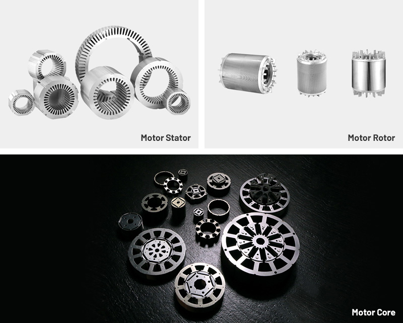
Within this context, Silent YX3 motor laminations have emerged as an essential component technology. These laminations are designed to suppress magnetic vibration, minimize mechanical resonance, and reduce audible noise during operation. With the YX3 motor platform widely adopted in Europe and Asia for high-efficiency applications, noise-optimized laminations offer manufacturers a tangible way to upgrade performance without redesigning the entire motor architecture.
From compressors and fluid pumps to precision conveyors and ventilation systems, OEMs increasingly require lamination materials and geometries that support both low-noise operation and stable magnetic performance. As a result, the demand for noise-optimized lamination stacks continues to grow across sectors where acoustic comfort, efficiency, and reliability must be simultaneously achieved.
Silent YX3 motor laminations are engineered using several tightly connected electromagnetic and mechanical principles:
The laminations guide the motor’s magnetic flux. Variations in thickness, steel grade, and insulation layer can create flux distortion, which leads to:
Magnetostriction noise
Vibrational resonance
Electromagnetic harmonics
Low-noise laminations stabilize flux density and suppress harmonic excitation.
Electrical steel inherently expands and contracts in sync with alternating magnetic fields. High-grade silicon steel with optimized grain orientation significantly reduces this magnetostrictive deformation, lowering audible noise generated inside the stator core.
The lamination stack behaves like a mechanical structure. Its damping properties depend on:
Stacking pressure
Interlayer insulation
Punching or laser-cutting quality
Residual stresses
Tightness of assembly
Noise-optimized laminations reduce natural frequencies that fall within audible bands (100–5,000 Hz).
Silent YX3 motor laminations incorporate tooth shapes, slot openings, and skew angles designed to:
Minimize cogging
Reduce torque ripple
Prevent synchronous vibration modes
These features directly influence both acoustic comfort and motor smoothness.
Silent YX3 motor laminations typically use premium electrical steels such as:
Low-carbon, non-oriented silicon steel (NOES)
Grain-oriented variants in specialized designs
High permeability grades with low core loss
Steel purity, grain size distribution, and silicon content (generally 2.8–3.2%) determine magnetic behavior and noise sensitivity.
To suppress eddy currents and reduce interlayer vibration, laminations use high-temperature organic or inorganic coatings providing:
Strong interlaminar resistance
Good adhesion
Mechanical damping
Electrical insulation stability
The coating thickness and uniformity significantly affect noise levels.
High-precision progressive dies ensure minimal burrs and consistent geometry. Excessive burrs can cause:
Flux leakage
Mechanical resonance
Higher magnetostriction noise
For prototypes or flexible production runs, laser cutting offers geometry precision, though heat-affected zones must be controlled to avoid inducing stress that increases noise.
Lamination stacks must maintain uniform compression. Poor stacking introduces micro-gaps that act as vibration amplifiers.
Stress-relief annealing restores magnetic permeability and reduces residual mechanical tension—both crucial for noise suppression.
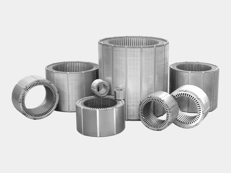
Silent YX3 motor laminations typically deliver:
Lower audible noise across medium-to-high load ranges
Reduced magnetostriction-induced vibration
Stable flux density with fewer harmonics
Lower iron loss, contributing to higher motor efficiency
Improved thermal behavior due to consistent magnetic properties
Several variables determine whether laminations achieve their intended noise-reduction performance.
Higher-grade silicon steel improves:
Magnetic flux uniformity
Permeability at operating frequency
Noise performance under varying loads
Inferior materials often create tonal noise at specific harmonic frequencies.
Burr height directly impacts:
Core loss
Magnetic harmonics
Structural noise
Industry benchmarks usually require burrs below 10–15 microns for noise-optimized applications.
A compromised insulation layer increases vibration transmission between laminations. Uniform coating improves damping and reduces acoustic peaks.
Consistent pressure ensures all laminations operate as one mechanical body, avoiding looseness that creates rattling or harmonic amplification.
Slot opening width, tooth tip radius, and core roundness influence both flux distribution and mechanical resonance zones.
OEMs evaluating suppliers for Silent YX3 motor laminations typically consider the following criteria:
Full traceability back to the steel mill ensures predictable magnetic and acoustic performance.
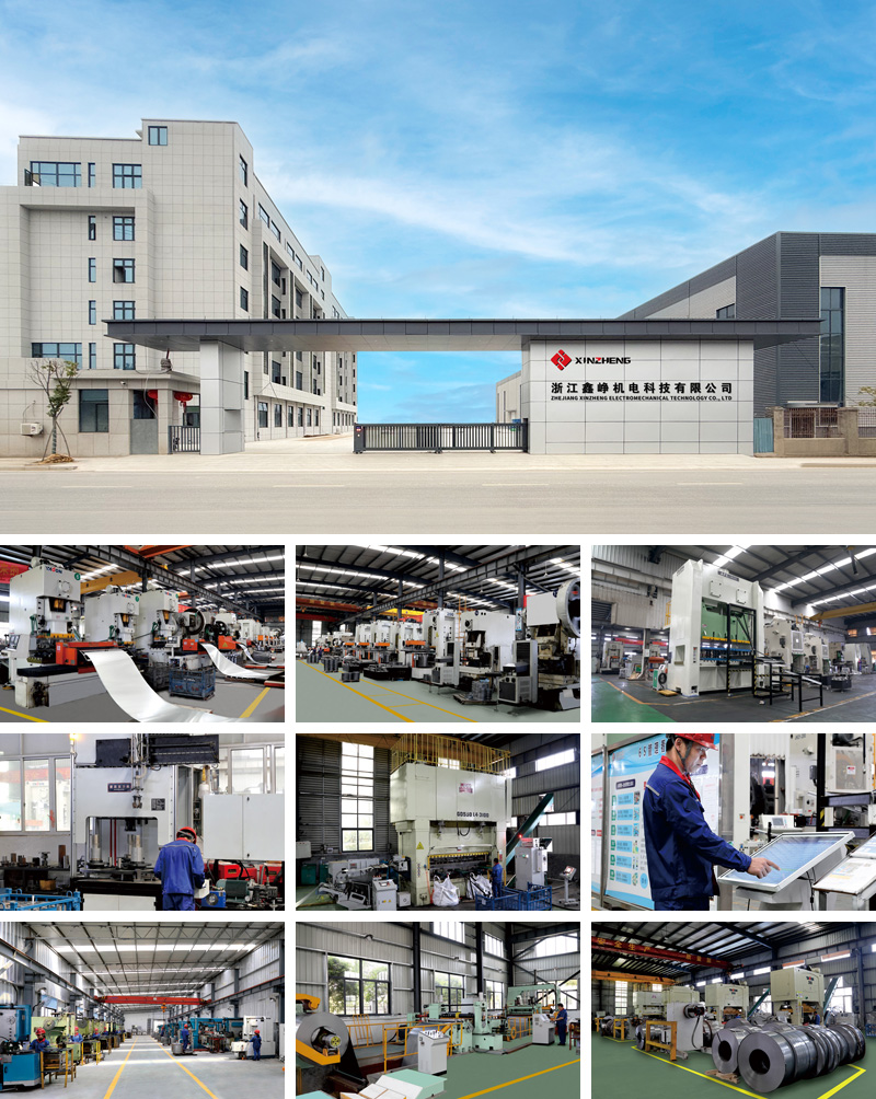
Suppliers should demonstrate:
Stable punching accuracy
Low burr generation
Controlled annealing cycles
Documented coating uniformity
Key testing includes:
Core loss analysis
Permeability measurement
Noise/vibration testing during sample runs
Residual stress detection
Suppliers offering design optimization—such as skewed slot analysis or harmonic simulation—provide added value for noise-critical applications.
Common standards may include:
IEC efficiency and noise limits
Material quality certifications
Environmental compliance for coating materials
Often caused by poor slot geometry, uneven stacking pressure, or low-grade silicon steel.
Tool wear or improper maintenance can introduce burr variations that degrade noise performance.
Inadequate coating flexibility leads to interlayer noise and increased eddy currents.
Materials with unstable grain structure can create pronounced vibration at 2nd or 3rd harmonics.
Variations in tooling alignment or press force lead to acoustic inconsistency among motors.
Silent YX3 motor laminations are widely used in noise-sensitive industrial and commercial applications.
Reduced tonal noise is essential for commercial buildings, hospitals, and data centers.
Acoustic performance directly affects workplace comfort and compliance with noise regulations.
In CNC machinery or robotics, vibration control contributes to higher accuracy and stability.
Silent laminations reduce cavitation-related vibration by minimizing motor-induced noise.
Low-noise motors improve overall product quality perception.
Users benefit from low-noise starts, stops, and steady-state operation.
Several trends are shaping the evolution of Silent YX3 motor laminations:
Advanced metallurgical processes are improving flux behavior with further reductions in magnetostriction noise.
Finite element analysis (FEA) and multi-physics modeling are increasingly used to simulate acoustic signatures before prototyping.
Bonding layers with precision lasers may replace mechanical riveting and improve damping.
As energy-efficiency targets rise, noise-optimized laminations will be integrated into next-generation ultra-high-efficiency platforms.
Coating materials and steel composition are shifting toward more sustainable formulations.
They use high-permeability steel, optimized slot geometry, and precise manufacturing to reduce magnetostriction vibrations and mechanical resonance.
Lower core loss and more stable magnetic flux reduce heat generation and improve energy conversion.
Yes. They maintain mechanical compatibility while upgrading noise and magnetic performance.
Core loss testing, burr measurement, noise analysis, coating integrity evaluation, and dimensional inspection.
Yes. Lower vibration reduces wear on bearings, couplings, and connected machinery.
Product Category
Comprehensive Strength

 Mobile: +86 13738592999
 Telephone: +86(576) 89307999
 E-mail: sales@zjxinzheng.com
 Address: Coastal Industrial City, Sanmen
County, Taizhou City, Zhejiang Province, China
Copyright © Zhejiang Xinzheng Electromechanical Technology Co., Ltd. All Rights Reserved.
This website uses cookies to ensure you get the best experience on our website.


 WhatsApp
 Phone
Phone